WGB
New Member
This is a somewhat long illustration of removing the rear end assembly intact with as minimal personal risk and muscle power as I can work out having spent a day and a half making up my version of the rear support jig
First the car has to be raised and I am fortunate in having my own hoist.
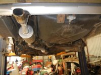
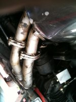
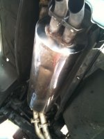
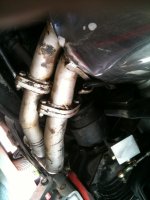
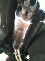
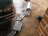
The most difficult part of the whole proceedings is removing the old exhaust system - finally with the assistance of an angle grinder it was managed.
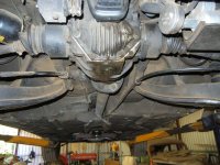
The heat shield must be removed to give access to the drive shaft and handbrake linkage
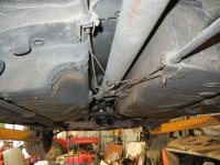
Linkage is undone and removed and the two rear cables are just left to hang
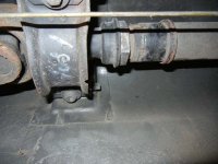
The drive shaft centre compression joint must first be loosened, The shaft has a 41mm hex on it and the compression part has a 46 mm hex.
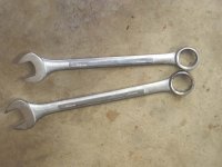
It would probably be possible to loosen the joint with adjustable spanners but here are the two spanners I used.
The rear flex joint needs to be unbolted at the driveshaft bolts and the driveshaft supported so that the universal joints are not damaged.
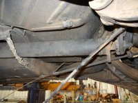
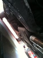
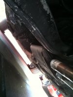
The driveshaft centre bearing is then unbolted and by pushing the shaft downwards and forwards the shaft can be pulled out of the pinion flex disk, After this the centre bearing bolts are put back in finger tight and the rear of the shaft is supported as shown here.
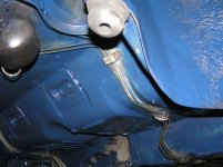
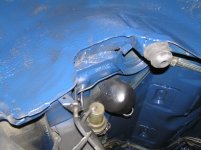
Brakelines at the flexible line joint and hydraulic strut lower ball joints in a 6.9 are separated.
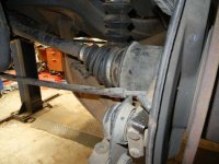
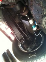
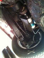
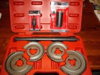
With a coill sprung rear end the shockabsorbers should be removed top and bottom (removing the rear seat) and a suitable spring compresser as shown below used to safely prevent personal injury.
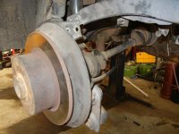
Sway bar at outer ends is unbolted from rear hub carrier
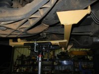
The weight of the subframe is taken by the jig mounted on the transmission jack
And then the front subframe mounts
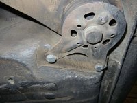
Followed by the four bolts that pass into the chassis at the rear diff mount are removed along with the connecting shaft for the the rear levelling valve.
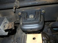
At this point the whole assembly gracefully allowed itself to be lowered with only a little assistance needed to part the front subframe mounts,
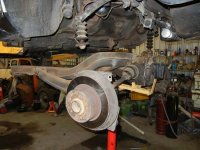
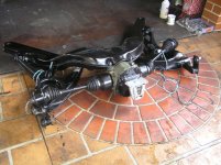
I transferred it to my engine crane
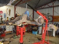
and placed it down in preparation for work
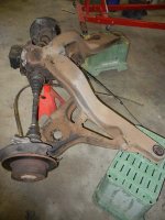
At this point one of the reasons I went to all this trouble is immediately apparent.
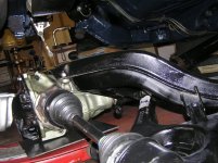
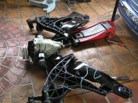
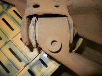
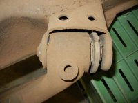
The outer diagonal arm bushes are worn and allowing the inside of each outer bush to wear metal on metal and obviously not doing a lot for the rear stability or geometry as well as making a few creaking noises.
The wear points are visible in the two pictures below and it has irritated me that I have failed twice before to change these bushes with the rear in-situ.
I will post part two as and when some further work is done.
Bill
First the car has to be raised and I am fortunate in having my own hoist.

The most difficult part of the whole proceedings is removing the old exhaust system - finally with the assistance of an angle grinder it was managed.

The heat shield must be removed to give access to the drive shaft and handbrake linkage

Linkage is undone and removed and the two rear cables are just left to hang
The drive shaft centre compression joint must first be loosened, The shaft has a 41mm hex on it and the compression part has a 46 mm hex.

It would probably be possible to loosen the joint with adjustable spanners but here are the two spanners I used.

The rear flex joint needs to be unbolted at the driveshaft bolts and the driveshaft supported so that the universal joints are not damaged.

The driveshaft centre bearing is then unbolted and by pushing the shaft downwards and forwards the shaft can be pulled out of the pinion flex disk, After this the centre bearing bolts are put back in finger tight and the rear of the shaft is supported as shown here.
Brakelines at the flexible line joint and hydraulic strut lower ball joints in a 6.9 are separated.

With a coill sprung rear end the shockabsorbers should be removed top and bottom (removing the rear seat) and a suitable spring compresser as shown below used to safely prevent personal injury.

Sway bar at outer ends is unbolted from rear hub carrier

The weight of the subframe is taken by the jig mounted on the transmission jack

And then the front subframe mounts

Followed by the four bolts that pass into the chassis at the rear diff mount are removed along with the connecting shaft for the the rear levelling valve.

At this point the whole assembly gracefully allowed itself to be lowered with only a little assistance needed to part the front subframe mounts,

I transferred it to my engine crane

and placed it down in preparation for work

At this point one of the reasons I went to all this trouble is immediately apparent.
The outer diagonal arm bushes are worn and allowing the inside of each outer bush to wear metal on metal and obviously not doing a lot for the rear stability or geometry as well as making a few creaking noises.
The wear points are visible in the two pictures below and it has irritated me that I have failed twice before to change these bushes with the rear in-situ.


I will post part two as and when some further work is done.
Bill

