WGB
New Member
The archilles heel of the M116 and M117 motor is the timing chain and many a good car will die an early death if the timing chain is not changed every 100,000 miles and particularly in conjunction with the plastic sliders and hydraulic tensioner with it's own plastic slider (Liner). It was also recommended that I change the camshaft sprockets as well as this would assist in getting the cam timing nearer correct.
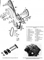
This is what you are endeavoring to replace.
I initially did this job in about 2005 and my expertise and tool supply has improved since this original pictorial was made.
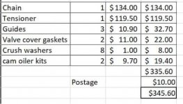
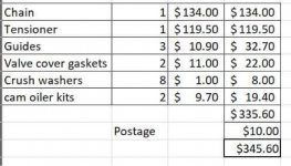
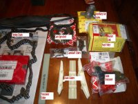
First job was to secure the parts and this is what was purchased along with some new Cam cover gaskets, a new auxillary air valve and a new fuel filter.
The air-cleaner, Sparkplugs,fan, Battery and battery holder, and radiator were removed and a bag was placed over the throttle body to stop any stray parts dropping into the engine.
At this stage I did not own a valve spring compressor and the job was done with the cam followers in place - so extreme care is needed to prevent valves meeting pistons with any force.
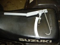
Latterly I manufactured a valve spring compressor as seen below and this makes the job much easier - just remember to keep any cam followers removed in order and placed back in their exact original positions.
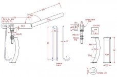
And here is a plan if you wish to fabricate your own.
The engine was turned clockwise (looking from the front of the car) on the crankshaft nut to TDC - never go backwards at all and if it isnecessary only 1 or 2 degrees to make something fit into place.
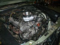
Next all the ancillaries including belts, pulleys, alternator, distributor and power steering were unbolted and removed. The position of the distributor at TDC was marked to make a good starting point for the timing at reassembly.
The power steering pump and reservoir were left connected to the pipework and tied to the side of the engine bay so as to spill as little oil as possible.
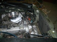
The camcovers were removed and on my car (with 168,000 recorded miles) the sprockets and sliders were original but the chain had been replaced at some time as it had a joining master link vbisible.
The chain stretch is measured by aligning the RH camshaft timing marks by rotating the motor with the crankchaft pulley nut (Clockwise only) using a socket, short extension and a large ratcheting torque wrench which I own.
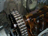
Here is a view of Right Hand Cam timing marks - in alignment
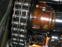
At the same time here is the Left hand cam alignment marks showing that the chain has stretched and that the sprockets are worn as the marks do not align.
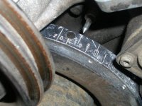
Again at the same time the crankshaft is reading 10 degrees after TDC - maximum chain stretch is 11 degrees ATDC on a 117 motor.
The next step is to change all the sliders, cogs and tensioner with it's own attached slider before the old chain is touched.
The sprockets and sliders can be removed without splitting the chain by removing the tensioner and giving sufficient slack for the sprockets to be removed.
They will need to be removed (One side at a time) to give enough clearance to remove and replace the sliders.
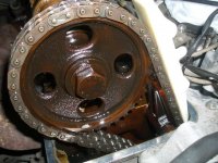
Here is a view of a new white coloured slider sitting on top of the chain to show the contrast with the old very dark brown slider in it's correct position
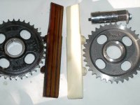
Here is a new slider and cog alongside an old slider and cog. There is a spark plug socket with a bolt through it which has been used as an extractor to remove a slider pin.
The pins (2 per slider) are held into the heads by friction only and are internally threaded to allow a bolt to be threaded into them for extraction. The factory method is to use a slide hammer on these attached bolts. The non-factory method is to use a nut on the thread of the correct sized bolt (M6) working against packing which is placed between nut and head material or if there is room the bolt is pulled through a spark plug spanner.
Another possibility is to purchase a "pin puller" off ebay as I did latterly which makes it easier again.
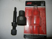
The pins are very tight and the surface of the head is not smooth so patience and different types of packing are used to get a straight pull if using nut and bolt method.
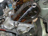
The left hand head has ribs on the front and here I have used an open ended spanner to keep the packing straight and am using the nut as the means of leverage.
To replace the sliders you will have to remove the sprockets whether you change them or not, just to give adequate clearance for removal and replacement of the slider pieces. You should use cable ties to hold the chain in position on the sprockets, then unbolt the sprockets while using a screwdriver through the sprocket hole to steady it and then keep the chain in tension so that it cannot move on the crankshaft sprocket .
The sliders are replaced and the pins driven back in with a bolt screwed into the end and gentle taps with a hammer.
The old chain tensioner is removed by removing the two bolts that locate it.
To remove the tensioner slider the lower pivot point has to be released. It is housed inside a cap low on the front of the motor. The cap is unscrewed and inside is a hollow pin which can be extracted by slipping a phillips head screwdriver into it and jiggling the tensioner arm and the screwdriver until it appears - may be worth tying a piece of wire to the top of the slipper so that it doesn't drop too far but from memory it can't drop right down.
The plastic lining of the tensioner slider is replaced by unclipping the old liner and clipping on a new one - locating lugs are moulded into the ends of the plastic liner.
While the tension is off the chain I replaced the Camshaft sprockets with new ones taking care to keep the teeth and keyway position in alignment.
The new tensioner was filled with oil and screwed in to keep the old chain in tension.
At this point the old chain was clamped to the RH sprocket with cable ties and the master link divided . I used newspaper to stop anything dropping into the motor.
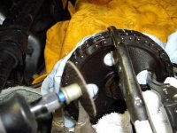
If there is an original chain with no master link a link must have it's peened ends ground off with a small grinder like a Dremel to enable it to be joined with the new chain.
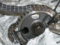
Here is the old cable joined to the new cable. The method calls for large re-usable cable ties but I didn't have any so I used a large packet of non-reusable ones and cut them when they needed to be removed. I found I needed two per time to stop the chain from slipping on the sprockets with the cam followers in position due to the force of the valve springs.
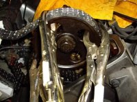
The next time I changed my 6.9 chain I used Vise-Grips which did not seem to mark the hardened metal of the chain and they did not need to be tightened all that tight to hold the chain.
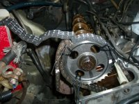
Here the new chain is being fed from the box sitting at the side of the engine bay while the old chain just continues to fall to the ground down the side of the motor with the crankshaft bolt being slowly turned clockwise.
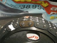
Here is the new master link with the new more robust tiny C-clamps - it's a real art to get these on without dropping anything - I again filled the space below with newspaper in case I dropped anything and had magnets on standby.
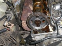
This shows the completed right hand cam tower with new chain, sprocket, slider, tensioner and tensioner slider all visible. Also visible are new plastic oiler fittings attached to the steel lines that run above the camshafts and lubricate them - mandatory replacement for only a few dollars more.
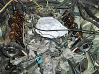
And here is the completed job - just needs the ancillaries and radiator put back again.
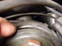
When the distributor is replaced there is a small groove in the side of the distributor body (visible when the plastic shield is lifted) which should line up with the rotor button so that if the motor is at TDC on the power stroke it will start with the ignition timing roughly set for startup.
The engine was quite different after the chain replacement - a lot of extra horsepower came from getting the timing right - total cost about $600 - in 2005 (original parts from Main agent were quoted at about $2300 at the same time).
Please do this to your own 3.5 and 4.5 motors before they expire.
6.9 motors have a ratcheting chain tensioner and are not prone to the same risk of instant and unannounced disaster as the smaller motors but many including mine can go up to 16 degrees of chain stretch with no symptoms other than some power loss. This is often why some motors are found with 2 degrees of chain advance as some backyard bodger has moved the chain forward 1 tooth on the cog = 18 degrees.
Bill
This is what you are endeavoring to replace.

I initially did this job in about 2005 and my expertise and tool supply has improved since this original pictorial was made.
First job was to secure the parts and this is what was purchased along with some new Cam cover gaskets, a new auxillary air valve and a new fuel filter.

The air-cleaner, Sparkplugs,fan, Battery and battery holder, and radiator were removed and a bag was placed over the throttle body to stop any stray parts dropping into the engine.
At this stage I did not own a valve spring compressor and the job was done with the cam followers in place - so extreme care is needed to prevent valves meeting pistons with any force.
Latterly I manufactured a valve spring compressor as seen below and this makes the job much easier - just remember to keep any cam followers removed in order and placed back in their exact original positions.

And here is a plan if you wish to fabricate your own.

The engine was turned clockwise (looking from the front of the car) on the crankshaft nut to TDC - never go backwards at all and if it isnecessary only 1 or 2 degrees to make something fit into place.

Next all the ancillaries including belts, pulleys, alternator, distributor and power steering were unbolted and removed. The position of the distributor at TDC was marked to make a good starting point for the timing at reassembly.
The power steering pump and reservoir were left connected to the pipework and tied to the side of the engine bay so as to spill as little oil as possible.

The camcovers were removed and on my car (with 168,000 recorded miles) the sprockets and sliders were original but the chain had been replaced at some time as it had a joining master link vbisible.
The chain stretch is measured by aligning the RH camshaft timing marks by rotating the motor with the crankchaft pulley nut (Clockwise only) using a socket, short extension and a large ratcheting torque wrench which I own.

Here is a view of Right Hand Cam timing marks - in alignment

At the same time here is the Left hand cam alignment marks showing that the chain has stretched and that the sprockets are worn as the marks do not align.

Again at the same time the crankshaft is reading 10 degrees after TDC - maximum chain stretch is 11 degrees ATDC on a 117 motor.
The next step is to change all the sliders, cogs and tensioner with it's own attached slider before the old chain is touched.
The sprockets and sliders can be removed without splitting the chain by removing the tensioner and giving sufficient slack for the sprockets to be removed.
They will need to be removed (One side at a time) to give enough clearance to remove and replace the sliders.

Here is a view of a new white coloured slider sitting on top of the chain to show the contrast with the old very dark brown slider in it's correct position

Here is a new slider and cog alongside an old slider and cog. There is a spark plug socket with a bolt through it which has been used as an extractor to remove a slider pin.
The pins (2 per slider) are held into the heads by friction only and are internally threaded to allow a bolt to be threaded into them for extraction. The factory method is to use a slide hammer on these attached bolts. The non-factory method is to use a nut on the thread of the correct sized bolt (M6) working against packing which is placed between nut and head material or if there is room the bolt is pulled through a spark plug spanner.
Another possibility is to purchase a "pin puller" off ebay as I did latterly which makes it easier again.

The pins are very tight and the surface of the head is not smooth so patience and different types of packing are used to get a straight pull if using nut and bolt method.

The left hand head has ribs on the front and here I have used an open ended spanner to keep the packing straight and am using the nut as the means of leverage.
To replace the sliders you will have to remove the sprockets whether you change them or not, just to give adequate clearance for removal and replacement of the slider pieces. You should use cable ties to hold the chain in position on the sprockets, then unbolt the sprockets while using a screwdriver through the sprocket hole to steady it and then keep the chain in tension so that it cannot move on the crankshaft sprocket .
The sliders are replaced and the pins driven back in with a bolt screwed into the end and gentle taps with a hammer.
The old chain tensioner is removed by removing the two bolts that locate it.
To remove the tensioner slider the lower pivot point has to be released. It is housed inside a cap low on the front of the motor. The cap is unscrewed and inside is a hollow pin which can be extracted by slipping a phillips head screwdriver into it and jiggling the tensioner arm and the screwdriver until it appears - may be worth tying a piece of wire to the top of the slipper so that it doesn't drop too far but from memory it can't drop right down.
The plastic lining of the tensioner slider is replaced by unclipping the old liner and clipping on a new one - locating lugs are moulded into the ends of the plastic liner.
While the tension is off the chain I replaced the Camshaft sprockets with new ones taking care to keep the teeth and keyway position in alignment.
The new tensioner was filled with oil and screwed in to keep the old chain in tension.
At this point the old chain was clamped to the RH sprocket with cable ties and the master link divided . I used newspaper to stop anything dropping into the motor.

If there is an original chain with no master link a link must have it's peened ends ground off with a small grinder like a Dremel to enable it to be joined with the new chain.

Here is the old cable joined to the new cable. The method calls for large re-usable cable ties but I didn't have any so I used a large packet of non-reusable ones and cut them when they needed to be removed. I found I needed two per time to stop the chain from slipping on the sprockets with the cam followers in position due to the force of the valve springs.

The next time I changed my 6.9 chain I used Vise-Grips which did not seem to mark the hardened metal of the chain and they did not need to be tightened all that tight to hold the chain.

Here the new chain is being fed from the box sitting at the side of the engine bay while the old chain just continues to fall to the ground down the side of the motor with the crankshaft bolt being slowly turned clockwise.

Here is the new master link with the new more robust tiny C-clamps - it's a real art to get these on without dropping anything - I again filled the space below with newspaper in case I dropped anything and had magnets on standby.

This shows the completed right hand cam tower with new chain, sprocket, slider, tensioner and tensioner slider all visible. Also visible are new plastic oiler fittings attached to the steel lines that run above the camshafts and lubricate them - mandatory replacement for only a few dollars more.

And here is the completed job - just needs the ancillaries and radiator put back again.

When the distributor is replaced there is a small groove in the side of the distributor body (visible when the plastic shield is lifted) which should line up with the rotor button so that if the motor is at TDC on the power stroke it will start with the ignition timing roughly set for startup.
The engine was quite different after the chain replacement - a lot of extra horsepower came from getting the timing right - total cost about $600 - in 2005 (original parts from Main agent were quoted at about $2300 at the same time).
Please do this to your own 3.5 and 4.5 motors before they expire.
6.9 motors have a ratcheting chain tensioner and are not prone to the same risk of instant and unannounced disaster as the smaller motors but many including mine can go up to 16 degrees of chain stretch with no symptoms other than some power loss. This is often why some motors are found with 2 degrees of chain advance as some backyard bodger has moved the chain forward 1 tooth on the cog = 18 degrees.
Bill
Last edited:

