WGB
New Member
After posting the first overhaul of my RH strut I have now completed my LH strut as well and with the benefit of hindsight here are some tricks.
1) Gently heat the top cover to melt the loctite and the top cover comes off with almost no resistance - the heat needed is not even enough to blister the paint.
I was advised to use a chain type pipe wrench and after some difficulty I obtained one but as it really puts most of it's pressure on only one area I feel a normal stillson type pipe wrench is the preferred option as it grips on two sides and is less likely to deform the tube.
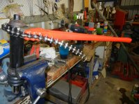
It is advisable to leave the old hydraulic hose in position while using the pipe wrench so that the seating face for the hose is not damaged by the pipe wrench.
2) the piston and rod is then pushed out the top and then the lower joint was heated - it really was only about four quick sweeps with the oxy torch - and again the paint was not even blistered.
The LH strut had a totally different design of piston to the right side with a piston ring and a more standard wrap around teflon seal as is often found in hydraulic cylinders.
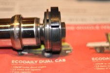
The LH bore was in much better condition than the right with a much lesser degree of polishing and no score marks. I elected not to hone it but merely put it back together again.
The right hand side I gave a very light hone with small honing stones dipped in kerosene with two squirts of oil in a 200ml container - it ended up with a very light 60 degree cross hatch- and also on the RH side I removed the glazing on the piston ring with 400 emery on a sheet of glass.
3) the main seal is driven out of the cylinder with a length of plastic pipe and the teflon seal with hidden o-ring tensioner is removed and replaced and the outer O ring seal replaced
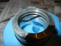
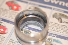
4) The lower teflon seal and O ring can then be replaced

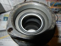
5) The piston is pushed back into the bore from the lower end of the cylinder ( The bore is shaped to allow this to happen easily without a need for any ring compressor) and after a couple of turns with emery to smooth the bottom end of the shaft then the main seal is lubricated and pushed over the shaft and into the cylinder, Lastly the lower seal is lubricated and pushed onto the shaft
Here the main seal is seated in the cylinder with the the lower seal now coming up the shaft
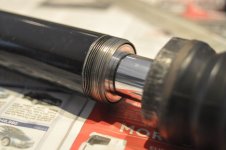
And here is the same stage with the view reversed to show the lower seal being pushed up the shaft with the lower end of the main seal about to seal on the fat lower O ring and tension the lower teflon seal
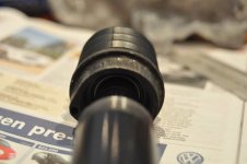
6) At this stage I would deviate from what I actually did on both my struts by screwing a liberally loctited cylinder onto the bottom joint using a pipe wrench on the dry upper joint cover without 0 ring or loctite.
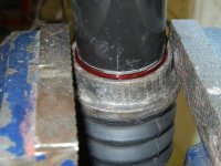
7) Then I would screw the top cover back on with a new O ring and lots of loctite.
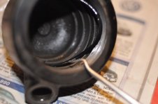
As you can see - the upper cover seals on the outside of the cylinder via it's O ring and does not need to be turned up tight to make a seal and the loctite will prevent it from turning.
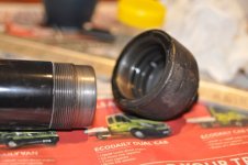
The reason for doing this is that if the two are tightened together and left that way the upper hose and bleed pipe are out of alignment ( as both of mine now are)
Here is a picture of my original right strut before removal
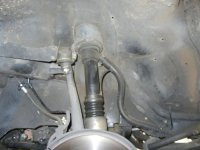
And here is a picture after replacement showing the misalignment - there seems to be plenty of length in the tube and it is no big deal but you might as well learn from my mistakes.
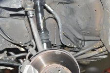
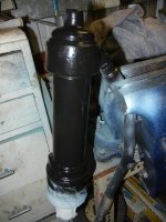
7) The strut is now refreshed externally - tool marks removed and re-painted.
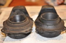
Here are some views of the old top mount and the new showing the depth of compression
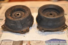
8) The new top mount is bolted up and the angle is critical - if the hose is rotated too far to the centreline the hose may foul on the mount when the strut compresses in future years and too far out and the hydraulic hose may rub on the tyre.
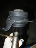
9) Bottom stone-shield is replaced and the lower ball joint is tightened using a thin 22 mm spanner while holding the stone shield.
The reason the stone shield holds the strut is that it's lower edge is double skinned with the inner skin having the shape of the lower part of the strut and thus acting as a spanner.
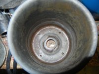
The strut is now replaced with a new hose and copper seal.
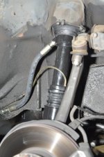
This picture of the LH side shows the position of the LH bleed tube but by the time I had worked it all out the loctite had set and it was too hard to go back.
I then replaced the wheels and started the car but try as I might the low pressure light would not go out so I decided to bleed the pump and it was while taking this photo demonstrating the pump being bled I noticed my disc was still in the "M" position (DUHH!!!).
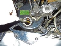
With the disc in the correct position the car pumped up immediately.
The reservoir was quite low so I put in my last remaining bottle of Hydraulic fluid and went for a 10 minute drive to Mundaring Weir.
The ride was significantly better with the new mounts and even better the car has stayed pumped up and not lost 1mm ( I have been measuring it each day while finding time to refit the rear seat) of height over the past three days.
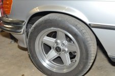
It has taken another 1 1/2 bottles of hydraulic oil to bring it up to the correct mark - not sure where it all went as it didn't seem to lose that amount.
I am looking forward to a longer drive and getting all the air out of the system.
Bill
1979 Euro 6.9 with AMG modifications #5554
1979 450SEL plus another 1979 for spares
1) Gently heat the top cover to melt the loctite and the top cover comes off with almost no resistance - the heat needed is not even enough to blister the paint.
I was advised to use a chain type pipe wrench and after some difficulty I obtained one but as it really puts most of it's pressure on only one area I feel a normal stillson type pipe wrench is the preferred option as it grips on two sides and is less likely to deform the tube.

It is advisable to leave the old hydraulic hose in position while using the pipe wrench so that the seating face for the hose is not damaged by the pipe wrench.
2) the piston and rod is then pushed out the top and then the lower joint was heated - it really was only about four quick sweeps with the oxy torch - and again the paint was not even blistered.
The LH strut had a totally different design of piston to the right side with a piston ring and a more standard wrap around teflon seal as is often found in hydraulic cylinders.

The LH bore was in much better condition than the right with a much lesser degree of polishing and no score marks. I elected not to hone it but merely put it back together again.
The right hand side I gave a very light hone with small honing stones dipped in kerosene with two squirts of oil in a 200ml container - it ended up with a very light 60 degree cross hatch- and also on the RH side I removed the glazing on the piston ring with 400 emery on a sheet of glass.
3) the main seal is driven out of the cylinder with a length of plastic pipe and the teflon seal with hidden o-ring tensioner is removed and replaced and the outer O ring seal replaced


4) The lower teflon seal and O ring can then be replaced


5) The piston is pushed back into the bore from the lower end of the cylinder ( The bore is shaped to allow this to happen easily without a need for any ring compressor) and after a couple of turns with emery to smooth the bottom end of the shaft then the main seal is lubricated and pushed over the shaft and into the cylinder, Lastly the lower seal is lubricated and pushed onto the shaft
Here the main seal is seated in the cylinder with the the lower seal now coming up the shaft

And here is the same stage with the view reversed to show the lower seal being pushed up the shaft with the lower end of the main seal about to seal on the fat lower O ring and tension the lower teflon seal

6) At this stage I would deviate from what I actually did on both my struts by screwing a liberally loctited cylinder onto the bottom joint using a pipe wrench on the dry upper joint cover without 0 ring or loctite.

7) Then I would screw the top cover back on with a new O ring and lots of loctite.

As you can see - the upper cover seals on the outside of the cylinder via it's O ring and does not need to be turned up tight to make a seal and the loctite will prevent it from turning.

The reason for doing this is that if the two are tightened together and left that way the upper hose and bleed pipe are out of alignment ( as both of mine now are)
Here is a picture of my original right strut before removal

And here is a picture after replacement showing the misalignment - there seems to be plenty of length in the tube and it is no big deal but you might as well learn from my mistakes.

7) The strut is now refreshed externally - tool marks removed and re-painted.

Here are some views of the old top mount and the new showing the depth of compression


8) The new top mount is bolted up and the angle is critical - if the hose is rotated too far to the centreline the hose may foul on the mount when the strut compresses in future years and too far out and the hydraulic hose may rub on the tyre.

9) Bottom stone-shield is replaced and the lower ball joint is tightened using a thin 22 mm spanner while holding the stone shield.
The reason the stone shield holds the strut is that it's lower edge is double skinned with the inner skin having the shape of the lower part of the strut and thus acting as a spanner.

The strut is now replaced with a new hose and copper seal.
This picture of the LH side shows the position of the LH bleed tube but by the time I had worked it all out the loctite had set and it was too hard to go back.

I then replaced the wheels and started the car but try as I might the low pressure light would not go out so I decided to bleed the pump and it was while taking this photo demonstrating the pump being bled I noticed my disc was still in the "M" position (DUHH!!!).

With the disc in the correct position the car pumped up immediately.
The reservoir was quite low so I put in my last remaining bottle of Hydraulic fluid and went for a 10 minute drive to Mundaring Weir.
The ride was significantly better with the new mounts and even better the car has stayed pumped up and not lost 1mm ( I have been measuring it each day while finding time to refit the rear seat) of height over the past three days.

It has taken another 1 1/2 bottles of hydraulic oil to bring it up to the correct mark - not sure where it all went as it didn't seem to lose that amount.
I am looking forward to a longer drive and getting all the air out of the system.
Bill
1979 Euro 6.9 with AMG modifications #5554
1979 450SEL plus another 1979 for spares
Last edited:
