WGB
New Member
When I rebuilt the front end of my 6.9 I found that the right hand front hub had had water ingress in it so I decided I wanted to check all other bearings in case the car had sat in water.
This meant that I wanted to strip all the rear bearings (and there are five in each side of a torque control rear hub) as well as replace the actual hub bearings as a matter of course. None of them were giving trouble but the kits are not expensive and it was too good an opportunity not to complete the job properly.
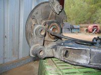
Here is a picture of the LH rear hub showing the complexity of the system as used in 450 and 6.9 rear ends.
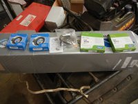
Here is a picture of the contents of one hub kit with two bearings, two seals and a new inner sealing ring, new crush ring, new locking tab for caliper, and new nut.
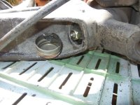
Here is the right rear wheel carrier cover popped and the retaining nut in view.
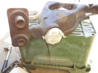
Here is the bare RH diagonal arm sealed against dirt ingress and ready for painting with bushes removed. Bushes will be another post when completed.
Hub with caliper carrier still in position.
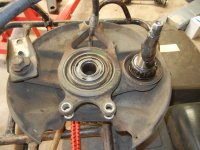
Retaining ring and protective cover of caliper carrier need to be removed.
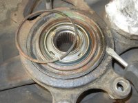
These two 10 mm hex bolts are bolted through the backing plate and into the caliper carrier and ned to be removed.
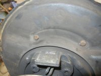
Caliper puller required quite extreme pressure to pop the bearing. I'm not sure the little 2 armed puller in the manual would work when they get old and rusty.
My 50mm socket with 1/2 inch converter in the end gives the correct distribution of pressure.
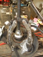
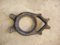
Here is the caliper carrier separated from the hub.
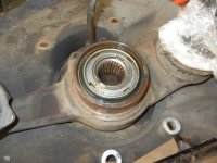
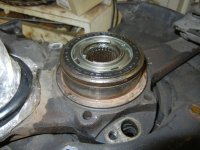
This is what is left and contains the hub bearing.
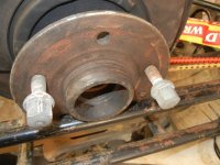
The manual calls for a bracket to hold the hub in a vice but I have used two old wheel studs clamped in the vice to accomplish the same thing.
Due to the torque involved - with the risk of distorting the hub - I am going to use one of my old discs to bolt up to the hub (with teh disc reversed) and that disc will have a flange welded to it to enable it to be held in a vise.
This is the approved rear hub special socket which fits the flat nut used in the rear hub.
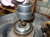
Even with that socket on a one metre bar it took all my bodyweight and arm strength to loosen the nut after bending back the holding crimps - this is why the hub needs to be supported securely if you are to have any chance of loosening it.
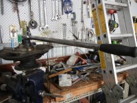
At this point they manual suggests using a puller to separate the two halfs of the hub but I could not get enough purchase with any puller I had and I cannot find the one I own (and I cannot find anyone who has one for sale) that resembles the one in the workshop manual so I resorted to my small press.
A 24 mm socket sits perfectly in the end of the shaft to give the necessary pressure point security.
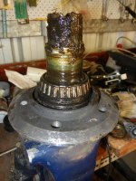
Here it is all cleaned up and a transmission gear puller being applied to pull off the outer bearing race.
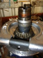
The puller is fully applied and the race is pulled off the axle.
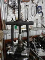
Only the bare axle remains.
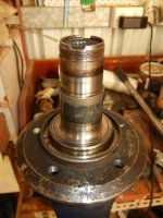
There is only a very small lip to get purchase when driving out the bearing races left in the hub but they came out easily enough with a mallet and an old screwdriver.
The old seal is also removed.
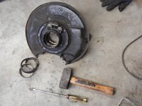
New races were driven in with my home collected brass drift .
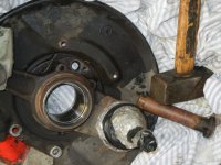
The outer radial seal had some sealant applied to it's insidemetal edge p and then driven on with a plastic hammer and then greased along with the races.
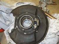
50 gm of high melting point grease was measured on scales and the races were packed and the remainder placed in the dead space between the races.
The inner race was tapped home and the inner radial seal was tapped home and the shaped washer pushed on and the nut turned finger tight only.
It needs to be tensioned correctly with a dial gauge once the rest of the hub is assembled and the whole assembly re-installed on the subframe.
That's for another day.
Bill
This meant that I wanted to strip all the rear bearings (and there are five in each side of a torque control rear hub) as well as replace the actual hub bearings as a matter of course. None of them were giving trouble but the kits are not expensive and it was too good an opportunity not to complete the job properly.
Here is a picture of the LH rear hub showing the complexity of the system as used in 450 and 6.9 rear ends.

Here is a picture of the contents of one hub kit with two bearings, two seals and a new inner sealing ring, new crush ring, new locking tab for caliper, and new nut.

Here is the right rear wheel carrier cover popped and the retaining nut in view.

Here is the bare RH diagonal arm sealed against dirt ingress and ready for painting with bushes removed. Bushes will be another post when completed.

Hub with caliper carrier still in position.

Retaining ring and protective cover of caliper carrier need to be removed.

These two 10 mm hex bolts are bolted through the backing plate and into the caliper carrier and ned to be removed.

Caliper puller required quite extreme pressure to pop the bearing. I'm not sure the little 2 armed puller in the manual would work when they get old and rusty.
My 50mm socket with 1/2 inch converter in the end gives the correct distribution of pressure.

Here is the caliper carrier separated from the hub.

This is what is left and contains the hub bearing.

The manual calls for a bracket to hold the hub in a vice but I have used two old wheel studs clamped in the vice to accomplish the same thing.
Due to the torque involved - with the risk of distorting the hub - I am going to use one of my old discs to bolt up to the hub (with teh disc reversed) and that disc will have a flange welded to it to enable it to be held in a vise.

This is the approved rear hub special socket which fits the flat nut used in the rear hub.

Even with that socket on a one metre bar it took all my bodyweight and arm strength to loosen the nut after bending back the holding crimps - this is why the hub needs to be supported securely if you are to have any chance of loosening it.

At this point they manual suggests using a puller to separate the two halfs of the hub but I could not get enough purchase with any puller I had and I cannot find the one I own (and I cannot find anyone who has one for sale) that resembles the one in the workshop manual so I resorted to my small press.
A 24 mm socket sits perfectly in the end of the shaft to give the necessary pressure point security.

Here it is all cleaned up and a transmission gear puller being applied to pull off the outer bearing race.

The puller is fully applied and the race is pulled off the axle.

Only the bare axle remains.

There is only a very small lip to get purchase when driving out the bearing races left in the hub but they came out easily enough with a mallet and an old screwdriver.
The old seal is also removed.

New races were driven in with my home collected brass drift .

The outer radial seal had some sealant applied to it's insidemetal edge p and then driven on with a plastic hammer and then greased along with the races.

50 gm of high melting point grease was measured on scales and the races were packed and the remainder placed in the dead space between the races.
The inner race was tapped home and the inner radial seal was tapped home and the shaped washer pushed on and the nut turned finger tight only.
It needs to be tensioned correctly with a dial gauge once the rest of the hub is assembled and the whole assembly re-installed on the subframe.

That's for another day.
Bill
